SWG series

- Products
- FORBLUE sunsep™
- Table of Products
- SWG series
Operating conditions
| Application | Dehumidification of sample gas for gas analysis | ||
|---|---|---|---|
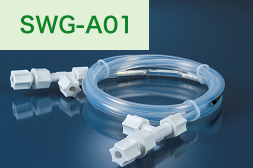
SWG-A01 series  |
|||
| Inlet fluid temperature | PP series | -15 ~ + 80℃ +5 to 176°F (Do not freeze) |
To maintain optimal dehumidification performance, we recommend that you minimize the difference between inlet (T inlet) and ambient (T ambient) temperatures, and operate within the following range : | Tinlet − Tambient | ≤ 5°C | Tinlet − Tambient | ≦9°F |
| KF series | -15 ~ + 100℃ +5 to 212°F (Do not freeze) |
||
| ambient temperature | PP series | -15 ~ + 80℃ +5 to 176°F (Do not freeze) |
|
| KF series | −15 to +100°C +5 to 212°F (Do not freeze) |
||
| Inlet Fluid Pressure Range |
|
||
| Purge gas: 0 to 0.05 MPa (gauge) (-6.0 to + 7.2psig at 77°F) | |||
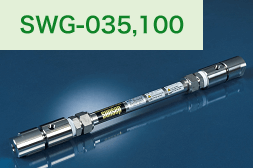
SWG-035 and 100 series  |
|||
| Inlet fluid temperature | PP series PS series SS series |
−15 to +60°C +5 to 140°F (Do not freeze) |
To maintain optimal dehumidification performance, we recommend that you minimize the difference between inlet (T inlet) and ambient (T ambient) temperatures, and operate within the following range : | Tinlet − Tambient | ≤ 5°C | Tinlet − Tambient | ≦9°F |
| ambient temperature | |||
| Inlet Fluid Pressure Range |
|
||
| Purge gas: −0.04 to 0.05 MPa (gauge) at 25°C (-6.0 to + 7.2psig at 77°F) | |||
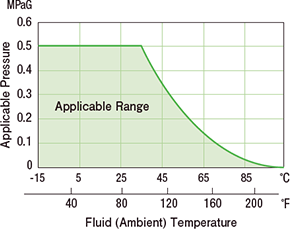
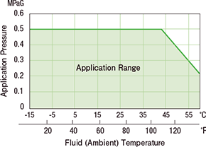
Note: The graphs above assume that the hollow fiber purge gas pressure is roughly the same as atmospheric pressure. The applicable pressure varies according to hollow fiber moisture or condensate mixing
Please contact us or your local representative if you are using a purge line with negative pressure, or in a pressurized atmosphere.
Standard specifications
| Model | Connector Material |
Standard Supply Flow Rate L/min.(ANR) (scfm) |
Length | Connector Size | Weight gf(lbs) |
||
|---|---|---|---|---|---|---|---|
| Total mm (inch) |
Purge Gas Port from Inlet to Outlet mm(inch) |
Supply gas inlet/outlet |
Purge gas inlet/outlet |
||||
| SWG-A01-03/PP | PP | ~2 (~0.07) |
390 (15.4) |
300 (11.8) |
Ø6.35mm (Ø1/4inch) |
Ø6.35mm (Ø1/4inch) |
40 (0.09) |
| SWG-A01-03/KF | PVDF | 55 (0.12) |
|||||
| SWG-A01-06/PP | PP | 690 (27.2) |
600 (23.6) |
50 (0.12) |
|||
| SWG-A01-06/KF | PVDF | 65 (0.15) |
|||||
| SWG-A01-12/PP | PP | 1290 (50.8) |
1200 (47.2) |
75 (0.17) |
|||
| SWG-A01-12/KF | PVDF | 90 (0.20) |
|||||
| SWG-A01-18/PP | PP | 1890 (74.4) |
1800 (70.9) |
100 (0.22) |
|||
| SWG-A01-18/KF | PVDF | 115 (0.25) |
|||||
| SWG-A01-24/PP | PP | 2490 (98.0) |
2400 (94.5) |
125 (0.27) |
|||
| SWG-A01-24/KF | PVDF | 140 (0.30) |
|||||
| SWG-A01-36/PP | PP | 3690 (145.3) |
3600 (141.8) |
175 (0.38) |
|||
| SWG-A01-36/KF | PVDF | 185 (0.41) |
|||||
| SWG-035-06/PP | PP | ~4 (~0.14) |
714 (28.1) |
600 (23.6) |
Rc1/4 (NPT1/4) |
Rc1/8 (NPT1/8) |
240 (0.53) |
| SWG-035-12/PP | PP | 1314 (51.7) |
1200 (47.2) |
350 (0.78) |
|||
| SWG-100-03/PS | PP | ~12 (~0.42) |
414 (16.3) |
300 (11.8) |
1000 (2.2) |
||
| SWG-100-03/SS | SUS316 | 1200 (2.65) |
|||||
| SWG-100-06/PS | PP | 714 (28.1) |
600 (23.6) |
1200 (2.65) |
|||
| SWG-100-06/SS | SUS316 | 1450 (3.20) |
|||||
| SWG-100-12/PS | PP | 1314 (51.7) |
1200 (47.2) |
1680 (3.71) |
|||
| SWG-100-12/SS | SUS316 | 1925 (4.25) |
|||||
Operating precautions
Supply gas
- To remove drainage, dust, etc., we recommend installing a filter (pore size ≤ 5 μm) at the supply gas inlet.
- When using a lubricated compressor, we recommend installing an automatic oil mist separator at the supply gas inlet side with filtration of ≤ 0.3 μm, 95% particle size collection rate, and oil-mist concentration of <1 mgf/Nm3.
- The supply gas should be clean and free of dust, corrosive gases, organic solvents, chemicals, and similar substances.
- When installing a pressure-reducing valve, we recommend installing the valve at the outlet side of the dryer to improve dehumidification efficiency.
Purge gas
- Purge gas is used to purge permeated water vapor from the outside of the hollow fiber membrane.
-
- The purge outlet should be opened to the atmosphere, or reduced or eliminated.
- Purge gas or sample gas should be discharged into harm-removing equipment or into a safe place.
- The purge flow rate control valve should always be installed upstream of the purge gas inlet.
Typical examples
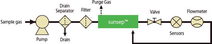
Using all sample gas as purge gas
- Effective if the sample gas flow rate is relatively low.
- The sample gases loses pressure as it passes through the analyzers. This pressure loss should be considered in determining the appropriate supply pressure.
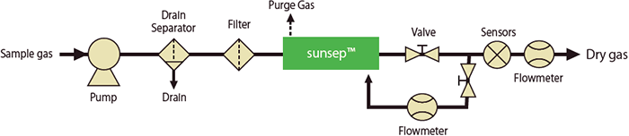
Using a portion of the sample gas as purge gas
- Effective if the sample gas flow rate is relatively high.
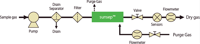
Supplying purge gas separately
- Effective if instrumentation air or dried nitrogen gas is supplied separately.
- Shows stable performance even if the supply pressure is lower than that of examples 1 and 2.
- Dehumidification performance depends on the dryness of the supplied purge gas.
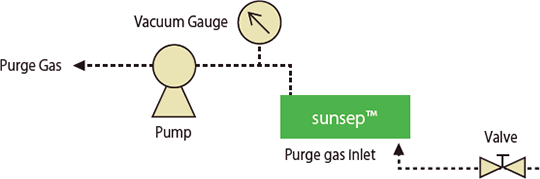
Vacuum purge line
- Sample schematic :