SWB/C/F series

- Products
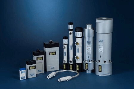
- FORBLUE sunsep™
- Table of Products
- SWB/C/F series
Operating conditions
| Application | Dehumidification of industrial compressed air and noncorrosive gas | |
|---|---|---|
| Inlet fluid temperature | −20 to +55°C (-4 to +131 °F) (Do not freeze) |
To maintain optimal dehumidification performance, we recommend that you minimize the difference between inlet (T inlet) and ambient (T ambient) temperatures, and operate within the following range: | T inlet − T ambient | ≤ 5°C (| T inlet - T ambient | ≦9°F) |
| Ambient temperature | −20 to +55°C (-4 to +131 °F) (Do not freeze) |
|
| Inlet fluid pressure | Supply gas: 0 to 0.85 MPa (gauge) / 0 to 120 psig | |
| Purge gas: 0 to 0.05 MPa (gauge) / 0 to 7 psig | ||
Standard specifications

| Model | Supply Gas Flow Rate L/min (ANR) (scfm) |
Dimensions mm(inch) |
Connector Size | Weight gf(lbs) |
Built-in purge circuit |
|||
|---|---|---|---|---|---|---|---|---|
| Supply gas inlet inlet/outlet |
Purge gas inlet/outlet |
|||||||
| SWB-01-100 | ~150 (~5.3) |
Φ=32 (1.3) |
L=240 (9.4) |
Rc1/4 (NPT1/4) |
Rc1/8 (NPT1/8) |
220 (0.49) |
- | |
| SWB-01-200 | ~100 (~3.5) |
Φ=32 (1.3) |
L=340 (13.4) |
275 (0.60) |
- | |||
| SWB-02-100 | ~300 (~10.6) |
Φ=50 (2.0) |
L=310 (12.2) |
Rc3/8 (NPT3/8) |
Rc1/2 (can be made compatible with NPT 1/2) |
625 (1.38) |
- | |
| SWB-05-100 | ~600 (~21.2) |
600 (1.33) |
- | |||||
| SWB-10-150 | ~1200 (~42.4) |
Φ=75 (3.0) |
L=340 (13.4) |
Rc1/2 (NPT1/2) |
- | 1400 (3.09) |
○ | |
| SWB-17-200 | ~1800 (~63.6) |
Φ=110 (4.3) |
L=370 (14.6) |
Rc1 (NPT1) |
- | 4810 (10.61) |
||
※*Supply gas flow rate data are based on the following operating conditions: Supply gas pressure: 0.7 MPa (102 psig), pressure loss between supply gas inlet and outlet ≤ 0.035 MPa (5.1 psig).

| Model | Supply Gas Flow Rate L/min (ANR) (scfm) |
Dimensions mm(inch) |
Connector Size | Weight gf(lbs) |
Built-in purge circuit |
||||
|---|---|---|---|---|---|---|---|---|---|
| Supply gas inlet inlet/outlet |
Purge gas inlet/outlet |
||||||||
| SWC-M04-70/OP | ~15 (~0.5) |
W=36 (1.4) |
H=75 (3.0) |
D=15 (0.6) |
M5 (Female) |
M5 (Female) |
50 (0.11) |
- | |
| SWC-M04-70/IP | - | ○ | |||||||
| SWC-M08-100 | ~50 (~1.8) |
W=61 (2.4) |
H=112 (4.4) |
D=31 (1.2) |
Rc1/8 (NPT1/8) |
- | 270 (0.59) |
○ | |
| SWC-M08-100/H*1 | |||||||||
| SWC-M15-100 | ~80 (~2.8) |
W=61 (2.4) |
H=112 (4.4) |
D=31 (1.2) |
Rc1/8 (NPT1/8) |
- | 270 (0.60) |
○ | |
| SWC-M15-100/H*1 | |||||||||
| SWC-01-150 | ~150 (~5.3) |
W=70 (2.8) |
H=153 (6.0) |
D=40 (1.6) |
Rc1/4 (NPT1/4) |
- | 345 (0.76) |
○ | |
| SWC-02-250 | ~300 (~10.6) |
W=100 (3.9) |
H=200 (7.9) |
D=50 (2.0) |
Rc3/8 (NPT3/8) |
- | 680 (1.50) |
○ | |
| SWC-03-250 | ~450 (~15.9) |
725 (1.59) |
○ | ||||||
| SWC-03-250/H*1 | |||||||||
※*Supply gas flow rate data are based on the following operating conditions: Supply gas pressure: 0.7 MPa (102 psig), pressure loss between supply gas inlet and outlet ≤ 0.035 MPa (5.1 psig).
*1: Low purge flow model

| Model | Supply Gas Flow Rate L/min (ANR) (scfm) |
Dimensions mm(inch) |
Connector Size | Weight gf(lbs) |
Built-in purge circuit |
|||
|---|---|---|---|---|---|---|---|---|
| Supply gas inlet inlet/outlet |
Purge gas inlet/outlet |
|||||||
| SWF-M06-400 | ~30 (~1.1) |
Dia=25 (1.0) |
L=516 (20.3) |
Rc1/4 (NPT1/4) |
Rc1/8 (NPT1/8) |
120 (0.27) |
- | |
*Supply gas flow rate data are based on the following operating conditions: Supply gas pressure: 0.7 MPa (102 psig), pressure loss between supply gas inlet and outlet ≤ 0.035 MPa (5.1 psig).
Operating instructions
Supply gas
- To remove drainage, dust, etc., we recommend installing a filter (pore size ≤ 5 μm) at the supply gas inlet.
- When using a lubricated compressor, we recommend installing an automatic oil mist separator at the supply gas inlet side with filtration of ≤ 0.3 μm, 95% particle size collection rate, and oil-mist concentration of <1 mgf/Nm3.
- The supply gas should be clean and free of dust, corrosive gases, organic solvents, chemicals, and similar substances.
- When installing a pressure-reducing valve, we recommend installing the valve at the outlet side of the dryer to improve dehumidification efficiency.
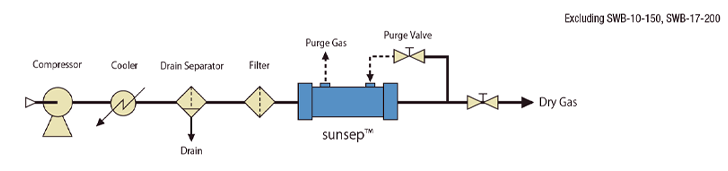
Purge gas
- Purge gas is used to purge permeated water vapor from the outside of the hollow fiber membrane.
- Excessive pressure should not be applied to the purge gas inlet and outlet (max. 0.05 MPa (gauge)) (max. 7.1 psig).
- For operation with a small amount of purge gas (less than 10/min (ANR) (0.35 scfm)), we recommend installing a small-aperture fixed orifice rather than a needle valve.
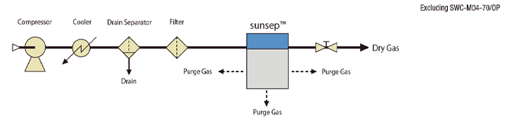
Models with Built-in Purge Circuits
- Models SWB-10-150, SWB-17-200 and SWC Series (excluding SWC-M04-70/OP) have built-in purge circuits.
- With these models, a part of the supply gas is automatically fed to the purge gas circuit. This eliminates the need for an outside purge line, simplifying installation and use.
- Purge gas can be discharged from the lower part of the housing or from the purge gas outlet. It is also possible to direct purge gas elsewhere by connecting a pipe to the outlet.
- For specific purge air flow rates, see the page for each products.
Purge rate
The ratio of purge gas flow rate to supply gas flow rate is referred to as the purge rate.
The typical purge gas flow ratio for sunsep™ is about 10-20% of the supply gas flow rate. In other words, 80-90% of the supply gas flow rate produces dehumidified gas.